A - S - Y - Z Parameter Conversion Calculator
What is an A, S, Y, Z Parameter Conversion Calculator?
An A-S-Y-Z parameter conversion calculator is a tool used in electrical engineering, specifically in network analysis of two-port electrical circuits. These parameters describe how voltage and current behave at the input and output terminals of a circuit and are essential for understanding, modeling, and designing complex electrical systems. Let's break down the parameters:
A-parameters (ABCD parameters): Also called transmission parameters, they describe the relationship between input and output voltage and current. They're widely used in transmission line analysis.
S-parameters (Scattering parameters): Used mainly in RF and microwave engineering, they describe how signals scatter when they encounter network elements — perfect for high-frequency analysis.
Y-parameters (Admittance parameters): Represent the admittance (inverse of impedance) behavior of the network. They're used in small-signal analysis and circuit modeling.
Z-parameters (Impedance parameters): Describe the impedance relationships of the network and are often used in low-frequency network analysis.
Why Use This Calculator?
Simplifies Complex Conversions: Manually converting between these matrices can get tedious and error-prone.
Saves Time: Quickly translates between different representations.
Ensures Accuracy: Uses established formulas to prevent mistakes.
Design and Analysis: Useful when designing matching networks, transmission lines, or amplifier circuits.
How Does the Calculator Work?
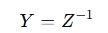
The calculator takes one set of parameters (like A, S, Y, or Z) and uses well-defined mathematical formulas to convert them into another set. Here's an example for converting between Z-parameters and Y-parameters:
Or for converting S-parameters to Z-parameters:
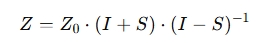
Where:
Z0 = Characteristic impedance
S = Scattering parameter matrix
I = Identity matrix
When Should You Use This Calculator?
RF and Microwave Circuit Design: Converting S-parameters to Z or Y for impedance matching.
Transmission Line Analysis: Using ABCD parameters for signal propagation and reflection calculations.
Amplifier Design: Converting between Y and Z parameters for stability and gain analysis.
Filter Design: Using admittance and impedance to model frequency response.