BJT Transistor Bias Voltage Calculator
What is a BJT Transistor Bias Voltage Calculator?
A BJT (Bipolar Junction Transistor) Bias Voltage Calculator is a tool used to calculate the required biasing voltages for a BJT transistor in an amplifier circuit or other electronic applications. Biasing ensures that the transistor operates in the correct region (usually the active region) for linear amplification or proper switching, and it helps stabilize the transistor's operating point.
Why Use It?
Stability: Biasing ensures the transistor operates at a steady point, even if there are changes in temperature or transistor parameters.
Linear Operation: In amplifiers, proper biasing is essential for the transistor to amplify signals linearly without distortion.
Optimized Performance: Helps achieve the desired performance (e.g., voltage gain, current gain) for the transistor in circuits like amplifiers, oscillators, or switches.
Preventing Saturation or Cutoff: Biasing ensures the transistor does not go into saturation or cutoff regions (where it would behave as a switch, not an amplifier).
How Does It Work?
To bias a BJT properly, you need to set up the base-emitter voltage (V_be) and collector-emitter voltage (V_ce). Typically, the calculator calculates the biasing voltages based on the DC operating point (also called Q-point), which ensures that the transistor remains in the active region.
Here are the key formulas used in biasing:
Base Voltage (V_b):
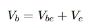
Where:
Vbe is the base-emitter voltage (typically around 0.7V for silicon BJTs).
Ve is the emitter voltage (calculated or defined in the circuit).
Collector Voltage (V_c):
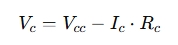
Where:
Vcc is the supply voltage.
Ic is the collector current.
Rc is the collector resistor.
Emitter Voltage (V_e) (for common-emitter biasing):
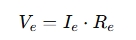
Where:
Ie is the emitter current (approximately equal to the collector current in many cases).
Re is the emitter resistor.
When to Use It?
Designing Amplifiers: When designing audio, RF, or signal amplifiers, proper biasing is critical for maximizing gain and linearity.
Biasing Transistors in Switching Circuits: For transistors used as switches, biasing ensures they fully turn on or off without staying in an intermediate state.
Stabilizing Operating Points: When temperature or power supply changes might affect the transistor's performance, biasing keeps it at the desired operating point.
Creating Oscillators: Proper biasing ensures the transistor operates in the correct region for oscillation.
Simulation and Testing: If you're testing a circuit on a simulator or building a prototype, the bias voltage calculator helps optimize the design.
Key Parameters to Input:
Supply Voltage (Vcc): The voltage available to the transistor circuit.
Collector Resistor (Rc): Resistor placed in the collector path that limits the collector current.
Emitter Resistor (Re): Resistor placed in the emitter path to stabilize the operating point.
Desired Collector Current (Ic): The current flowing through the collector, which typically determines the signal amplification.
Base-Emitter Voltage (Vbe): Usually fixed (e.g., around 0.7V for silicon transistors) but may vary depending on the specific transistor.
Example Scenario:
If you're designing a small-signal amplifier using a BJT, you can use the calculator to:
Set the desired collector current.
Input the supply voltage (Vcc).
Calculate the biasing voltages (base voltage, emitter voltage, and collector voltage) to ensure the transistor stays in the active region and amplifies the input signal linearly.