Butterworth Pi LC High Pass Filter Calculator
A Butterworth Pi LC High-Pass Filter Calculator is a design tool used to create a Butterworth high-pass filter in a π (pi) configuration using inductors (L) and capacitors (C). This type of filter allows high-frequency signals to pass while attenuating low-frequency signals — and it's known for its maximally flat response in the passband, meaning there's no ripple before the cutoff frequency.
Structure of the Pi LC High-Pass Filter:
The "π" shape comes from how the components are arranged:
Two inductors (L1, L2) in parallel (shunted to ground).
One capacitor (C) in series between the inductors.
This setup resembles the Greek letter "π".
How it works:
High frequencies: Pass easily through the series capacitor while being blocked by the shunt inductors.
Low frequencies: Face high impedance from the capacitor and are absorbed by the inductors, reducing their amplitude.
What the calculator does:
The tool determines the optimal values for the inductors and capacitor based on key parameters:
Cutoff frequency (Fc): The frequency below which signals are attenuated.
Load impedance (Z): The impedance of the connected load.
Filter order: Number of LC stages — higher order = sharper roll-off.
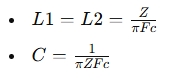
For a second-order Butterworth high-pass filter, the formulas often look like:
Why choose a Butterworth Pi High-Pass Filter?
Pros:
Flat passband: No ripple before the cutoff frequency.
Predictable roll-off: A good balance between smoothness and attenuation.
Cons:
Slower roll-off: Not as steep as Chebyshev or elliptic filters.