Op Amp Low Pass Filter Calculator
An Op Amp Low Pass Filter Calculator is a tool used to calculate the characteristics of a low-pass filter circuit that is built using an operational amplifier (op-amp). A low-pass filter allows low-frequency signals to pass through while attenuating (reducing the amplitude of) higher-frequency signals.
What is an Op Amp Low Pass Filter?
An Op Amp Low Pass Filter is a type of electronic filter that uses an op-amp along with resistors and capacitors to allow low-frequency signals to pass while filtering out higher-frequency signals. It is designed to provide a smooth output by blocking high-frequency noise and only allowing the low-frequency component of the signal to pass through.
This filter typically has a cutoff frequency fcf_c f c , which is the frequency at which the output signal starts to attenuate by 3 dB (or approximately 70.7% of its maximum value).
Why Use an Op Amp Low Pass Filter?
- Noise reduction: Low-pass filters are used to remove high-frequency noise from signals, especially in systems like audio or communication circuits.
- Signal smoothing: In applications where signals need to be smoothed or filtered, such as audio or analog signals, low-pass filters help eliminate unwanted high-frequency components.
- Frequency selection: If you only want to pass frequencies below a certain threshold (e.g., in audio systems, power supplies, etc.), a low-pass filter ensures that only the desired frequencies are allowed to pass through.
- Protection: In certain circuits, low-pass filters can be used to protect sensitive components from high-frequency interference or oscillations.
How Does an Op Amp Low Pass Filter Work?
An op-amp low-pass filter typically consists of:
- Resistor (R): The resistor sets the time constant of the filter and defines the frequency response.
- Capacitor (C): The capacitor determines the cutoff frequency of the filter and works with the resistor to define the filter’s behavior.
- Op-Amp: The operational amplifier amplifies the signal and provides the necessary gain for the circuit to operate effectively.
The filter works by allowing signals with a frequency below a certain cutoff frequency to pass through with minimal attenuation. As the input frequency increases, the output signal starts to attenuate, and above the cutoff frequency, the signal is significantly reduced.
Op Amp Low Pass Filter Calculation:
The most important parameter in a low-pass filter is the cutoff frequency fcf_c f c , which determines where the filter begins to attenuate the signal.
Cutoff Frequency Formula:
For a single-pole low-pass filter (the most common type), the cutoff frequency is calculated as:

Where:
- fc = cutoff frequency (in Hz)
- R= resistance (in ohms, Ω)
- C = capacitance (in farads, F)
Example:
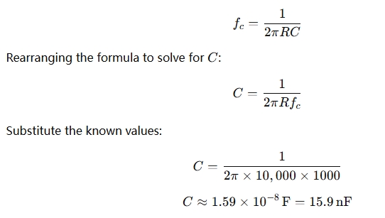
If you want to design a low-pass filter with a cutoff frequency of 1 kHz (1000 Hz), and you have a resistor of 10 kΩ, you can calculate the necessary capacitor value:

So, to create a low-pass filter with a cutoff of 1 kHz, you would need a 15.9 nF capacitor in combination with the 10 kΩ resistor.
When Should You Use an Op Amp Low Pass Filter Calculator?
- When designing filters: If you need to design an op-amp low-pass filter for a specific application, you can use the calculator to select the correct resistor and capacitor values based on your desired cutoff frequency.
- Noise filtering: In systems where you need to remove high-frequency noise from an audio or sensor signal, a low-pass filter is used to smooth the signal.
- Audio processing: In audio circuits, such as in equalizers, bass amplifiers, or speaker crossovers, low-pass filters help isolate low frequencies.
- Signal conditioning: Low-pass filters are used in signal processing to condition the signal before further amplification or conversion.
- Power supplies: In power supply circuits, low-pass filters are used to smooth out ripple or high-frequency noise.
Types of Low Pass Filters:
- First-order low-pass filter: The most basic type, with a simple resistor and capacitor. It attenuates the signal at a rate of 20 dB per decade after the cutoff frequency.
- Second-order or higher filters: These filters use more complex configurations and components (such as multiple capacitors or inductors) to achieve steeper roll-offs and more precise control over the frequency response.
Practical Applications:
- Audio systems: Used in audio amplifiers and equalizers to filter out high-frequency noise and isolate bass frequencies.
- Sensor signal conditioning: Low-pass filters are commonly used to smooth sensor outputs, such as temperature or pressure readings, before they are processed.
- Power supplies: Used in DC power supplies to smooth out ripple or noise from the output signal.
- Communication systems: Used in radio frequency (RF) systems to filter out unwanted high-frequency signals and noise.
- Signal processing: Low-pass filters are part of larger signal conditioning systems, such as in analog-to-digital conversion circuits.