IC 555 Timer Calculator
An IC 555 Timer Calculator is a tool that helps you calculate the timing characteristics (such as frequency, duty cycle, and time period) of circuits built around the 555 timer IC. The 555 timer is one of the most versatile and widely used integrated circuits in electronics, capable of generating precise timing pulses, oscillations, and delays in various configurations such as astable, monostable, and bistable modes.
What Is It?
The 555 Timer is a highly stable IC used for generating precise time delays or oscillations in various applications. It can be configured in different modes, depending on the circuit's needs:
Monostable Mode: Generates a single pulse of fixed duration when triggered.
Astable Mode: Functions as an oscillator, generating continuous square waves (e.g., for clock pulses or PWM signals).
Bistable Mode: Works as a flip-flop, maintaining one of two stable states until triggered to change.
The 555 Timer Calculator helps you calculate key parameters for these modes, such as:
Frequency (the rate at which the output oscillates)
Pulse Width (duration of high or low output)
Duty Cycle (the proportion of time the output is high during a period)
Why Use an IC 555 Timer Calculator?
Ease of Design: It allows you to quickly calculate the values of resistors and capacitors needed for a specific output frequency, pulse width, or duty cycle in your circuit.
Precision: It helps you achieve the desired time delay, frequency, or waveform, ensuring your 555 timer circuit behaves exactly as needed.
Efficiency: It saves time by automating the complex calculations associated with the 555 timer formulas, especially when designing circuits or troubleshooting.
Learning and Experimentation: If you're experimenting with different configurations of the 555 timer, the calculator allows you to instantly see how changing component values affects the output.
How Does It Work?
The IC 555 Timer Calculator typically uses the following formulas for the different modes of operation:
Monostable Mode (Single Pulse):
The time period for a single pulse in monostable mode is given by:
T=1.1×R×C
Where:
T is the time duration of the pulse (in seconds),
R is the resistance (in ohms),
C is the capacitance (in farads).
Astable Mode (Oscillator):
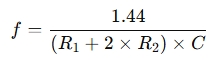
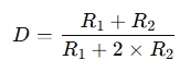
The frequency and duty cycle in astable mode depend on two resistors (R1, R2) and a capacitor (C):
Frequency:
Duty Cycle:
Where:
f is the frequency of oscillation (in Hz),
D is the duty cycle (as a percentage),
R1 and R2 are resistances (in ohms),
C is the capacitance (in farads).
Bistable Mode (Flip-Flop):
Bistable mode is used for storing and switching between two states, and it doesn't require a timing calculation like monostable or astable modes. However, it can be used in conjunction with other components to form memory storage or state-based circuits.
The calculator automatically applies these formulas to the entered values (resistors, capacitors, or desired output frequency) and outputs the calculated results.
When Do You Use an IC 555 Timer Calculator?
When Designing Oscillators: If you need to create a precise frequency for a clock pulse, tone generator, or signal generator, the calculator can quickly give you the right component values.
For Time Delay Circuits: When designing circuits that require a specific delay (e.g., a time delay relay), the calculator will help determine the exact resistor and capacitor values.
For Pulse Width Modulation (PWM): If you need to create a PWM signal for motor control, LED dimming, or signal modulation, the calculator helps you fine-tune the duty cycle and frequency.
In Educational Settings: If you're learning about or teaching timing circuits, the calculator helps quickly visualize how changes in component values affect the output.
When Prototyping: When building or testing circuits, a 555 Timer Calculator provides a fast way to adjust parameters, test configurations, and avoid mistakes in timing calculations.
Example Scenario:
If you're designing a simple LED flasher circuit with a 555 timer in astable mode and you want the frequency to be 1 Hz (one flash per second), you can use the calculator to input the desired frequency and calculate the necessary resistor and capacitor values. After adjusting your components, you'll have a 1 Hz square wave output to control the LED's on/off cycle.
In summary, an IC 555 Timer Calculator is an essential tool for simplifying the design and calculation of timing circuits using the 555 timer IC, saving you time and ensuring precision in your projects. Whether you're working with oscillators, pulse generators, or time delays, it helps you quickly determine the correct component values for your desired outcome.