Non-Inverting Operational Amplifier Resistor Calculator
What is a Non-Inverting Operational Amplifier Resistor Calculator?
A non-inverting operational amplifier (op-amp) is a fundamental circuit configuration where the input signal is applied to the non-inverting (+) terminal of the op-amp, and the output signal is in phase with the input. A resistor calculator for this circuit helps determine the resistor values required to achieve a specific voltage gain.
For a non-inverting op-amp, the voltage gain Av is:
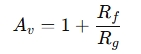
Where:
Av = Voltage gain (always positive — no phase inversion)
Rf = Feedback resistor (from the output to the inverting input)
Rg = Grounding resistor (from the inverting input to ground)
Why Use a Non-Inverting Op-Amp Resistor Calculator?
Simplifies Circuit Design: Quickly find resistor values for a required gain.
Avoids Manual Errors: Reduces mistakes in calculations, especially for multiple stages.
Saves Time: Speeds up the design and prototyping process.
Optimizes Performance: Ensures the right gain without distortion or overdriving components.
How Does the Calculator Work?
You typically input:
Desired voltage gain (Av)
One known resistor value ( Rf or Rg )
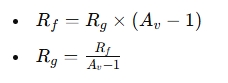
The calculator solves for the missing resistor:
When Should You Use This Calculator?
Amplifying weak signals from sensors, microphones, or transducers.
Buffering circuits to avoid loading effects.
Voltage followers when Av =1 for impedance matching.
Audio and signal processing applications where phase accuracy matters.